A Simplify command overview
This unit will teach you how to access the Simplify command and walk you through the user interface.
Any referenced datasets can be downloaded from "Module downloads" in the module overview.
Generate a simplified substitute model state - Exercise
The first goal in this exercise is to generate a simplified substitute model state of the Packing Machine assembly.
Task 1: Create a simplified substitute model state
- Open _packing machine.iam from the supplied dataset.
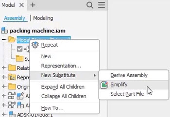
- In the Model Browser, right-click on the Model States folder and notice that New Substitute>Simplify is not available. This is because the large assembly was loaded in Express Mode. Press <Esc> to finish this step.
- In the Assemble tab>Express panel, click Load Full.
- In the Model Browser, right-click again on the Model States folder and select New Substitute>Simplify.
- At the top of the Simplify palette, set the preset drop-down to No Preset. Leave the Input options as the defaults.
- Under Replace with Envelopes, do the following:
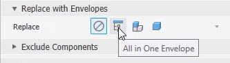
- Select All in One Envelope. Note the single bounding box representing the entire assembly. This would be useful for common space reservations.
- Change the option to Each Top Level Component. This creates bounding boxes for each top-level part or assembly.
- Change the option to Each Part. This creates a bounding box for each individual part in the entire assembly.
- Change the option back to None. This is the option you will use for this exercise.
- Select All in One Envelope. Note the single bounding box representing the entire assembly. This would be useful for common space reservations.
- Under Exclude Components, do the following:
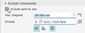
- Activate the option to Exclude parts by size.
- Set the Max. Diagonal value to 200mm. Note the number of components being excluded.
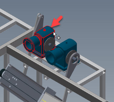
- Click the measure icon to the right of the Max. Diagonal value and select the housing shown below. Notice the change in the Max. Diagonal value and the total number of components excluded.
- Make sure Parts selection is active and the Select All Occurances option is OFF.
- Select a single package envelope, as shown below.
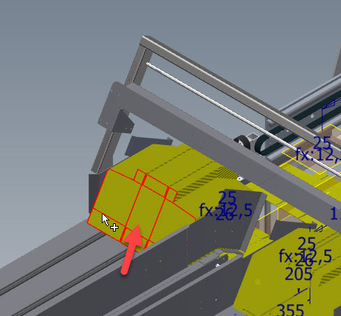
- Turn on the Select All Occurrences option.
- Select another occurrence of the package envelope. Notice how all occurrences are selected and are excluded.
- Click the icon for Show excluded parts to the right of the Exclude count readout. This will temporarily reverse the display, showing the excluded components.
- Select the one of the mounting feet, as shown below.
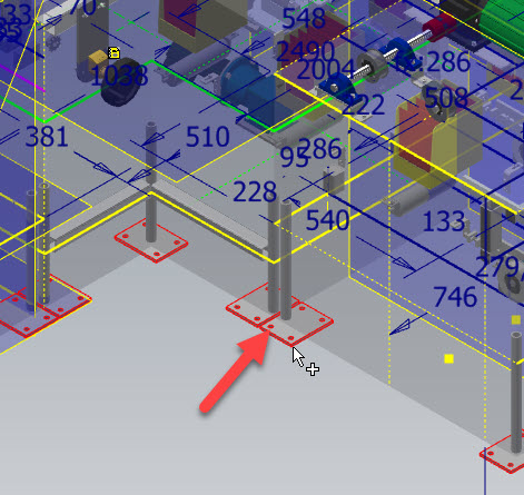
- Click the icon to Show included parts. This will set the display back to showing only parts that will be included in the final view. Notice the feet are now included.
- Continue to select parts to exclude. Select all the belts in the design.
- Under Remove Features, do the following:
- For Hole, select All, then click Highlight. Notice the number of holes that will be removed from the final view.
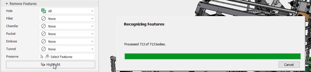
- For Fillet, select Range and set the value to 15mm. Click Highlight again. Notice the number of fillets that will be removed from the final view.
- For Chamfer, select Range and set the value to 10mm. Click Highlight again. Notice the number of chamfers that will be removed from the final view.
- For Pocket, select All. Click Highlight again and notice the number of pockets removed.
- For Emboss, select All. Click Highlight again and notice the number of emboss features removed.
- For Tunnel, select All. Click Highlight again and notice the number of tunnels removed.
- Notice that you can manually select features with the Preserve option if they need to be included in the final view.
- For Hole, select All, then click Highlight. Notice the number of holes that will be removed from the final view.
- Under Output, do the following:
- Note that Substitute is the only option allowed at this point.
- For Template, select the Standard (mm).ipt part template.
- Notice the default file name. You may change the default name if desired.
- Notice the save location. You may change this location if desired.
- Notice the BOM Structure option. You may change this if desired.
- Notice the options for Style. Set the Style to Maintain each solid as a solid body, which will create a single multibody part.
- Under Advanced Properties, do the following:
- Select Break link so this new component will not update if the main assembly is modified.
- Select Rename to change the component names in the final part and protect your internal naming practices from outside observations.
- Select Fill internal voids to remove any internal detail not previously addressed.
- Select Remove internal parts. This will exclude any internal parts obscured by larger external components.
- Select Use color override from source components to apply the color of the original pars to the new bodies.
- Select Make independent bodies on failed Boolean to generate new bodies if merging parts fail.
- Click OK to execute the overall command. This operation will take a few moments to complete.
- Toggle between the Primary and Substitute model states and notice the number of parts loaded into the model window.
Task 2: Export a Revit model
The next goal in this exercise is to export a Revit model that represents a simple bounding box for the entire machine. This file will be sent to the architectural team to be included in their building layout.
- Activate the Primary model state by double-clicking on it in the Model Browser.
- In the Assemble tab>Express panel, click Load Full. The model must be fully loaded to utilize the Simplify command.
- In the Assemble tab>Simplification panel, click Simplify.
- In the Simplify palette, under Replace with Envelopes, select All in One Envelope.
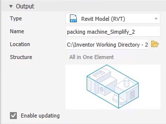
- Under Output, do the following:
- Select Revit Model (RVT) from the Type drop-down list.
- Use the default name. This can be changed if desired.
- Use the default location. This can be changed if desired.
- Confirm that Enable updating is selected. This will place a link in the Model Browser for future updates, if required.
- Under Advanced Properties, do the following:
- Select Fill internal voids.
- Select Remove internal parts.
- Select Use color override from source components.
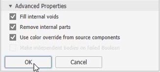
- Click OK to execute the command. This operation could take a few moments to complete, and you may be prompted to install the Revit interoperability for Inventor.
- Notice the Revit Export folder in the Model Browser. This is where the link to the Revit file is displayed. This link provides the update functionality, if required.
- Save and close all files.